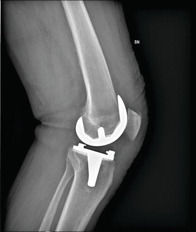
I designed a cruciate-retaining femoral component of a knee implant. A real-life example is shown below (top half component, DOI: 10.5772/intechopen.74024).
In the design process, there were several considerations:
- Joint Stability: High is good. A higher radius of curvature will lead to lower range of motion, which can improve joint stability.
- Range of Motion: 120˚ RoM is good but since patient demographics is usually older, joint stability should take priority.
- Stress/Strain Distribution: there’s less wear on the implant if there’s a higher spread of stress/strain across points of interest and their maximum values are low.
- Bone Resection Geometry: it’s easier for orthopaedic surgeons to implant the device if there are fewer cuts. This can reduce the length of surgery, which can decrease postoperative complications.
- Design Complexity: less complexity can lead to less variations in manufacturing, which make it easier for the quality of implants to be consistent. This can be quantified by the number of fillets, the number of arcs (as opposed to straight lines), and the symmetry of specific parts.
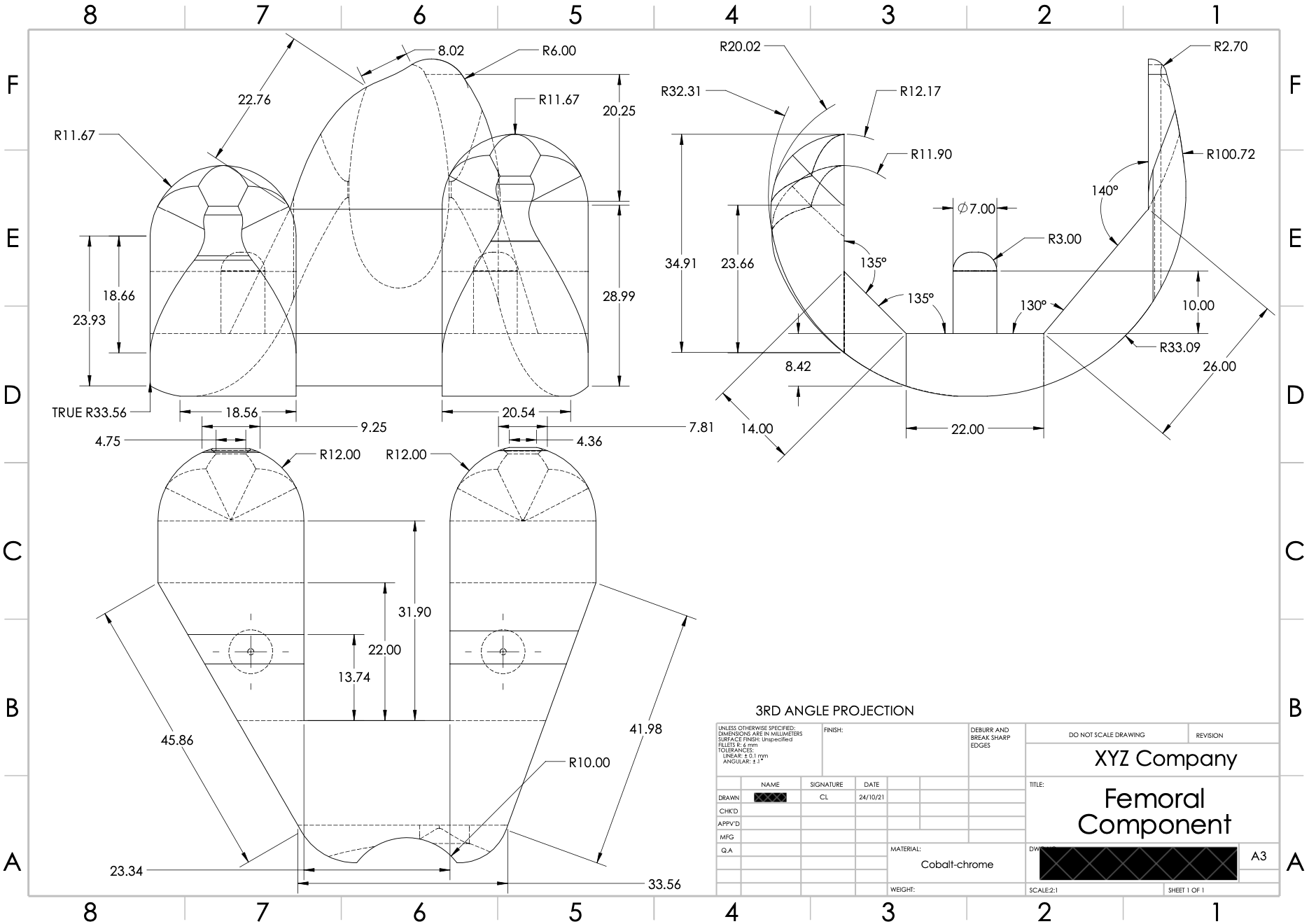
Below is the engineering parts drawing document of the design (made with SolidWorks):
- Joint stability is bit hard to assess from design (and with no tibial / other components of a knee implant).
- RoM is bit hard to assess from design (and with no tibial / other components of a knee implant).
- Stress/Strain Distribution is explored further below.
- Bone Resection Geometry: 5 cuts need to be made on the femur to implant the device; angles range from 130˚ to 140˚.
- Design Complexity: Looks a bit complicated but I think it should be alright!
Quick note on material choice: cobalt-chrome alloy was chosen as it has high strength and high corrosion/wear resistance. But careful to use it for the other components of the knee implant as metal-on-metal replacements can cause cobalt leak and poisoning.
The stress/strain distribution was assessed using ANSYS FEA simulation. Some assumptions were made:
- Point loading of 500 N each at the centre of two femoral condyles (anatomical structures at the end of the femur where they integrate with the knee implant).
- Femoral condyles are made completely of cortical bone.
- Perfect integration of femoral component with underlying bone.
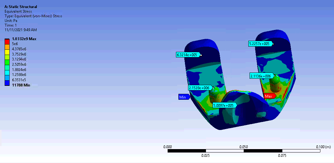
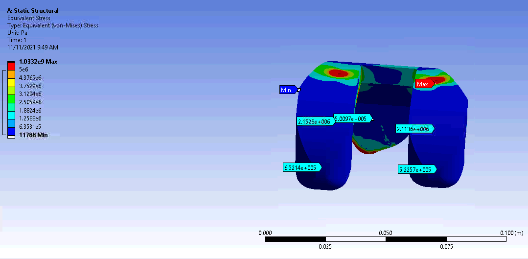
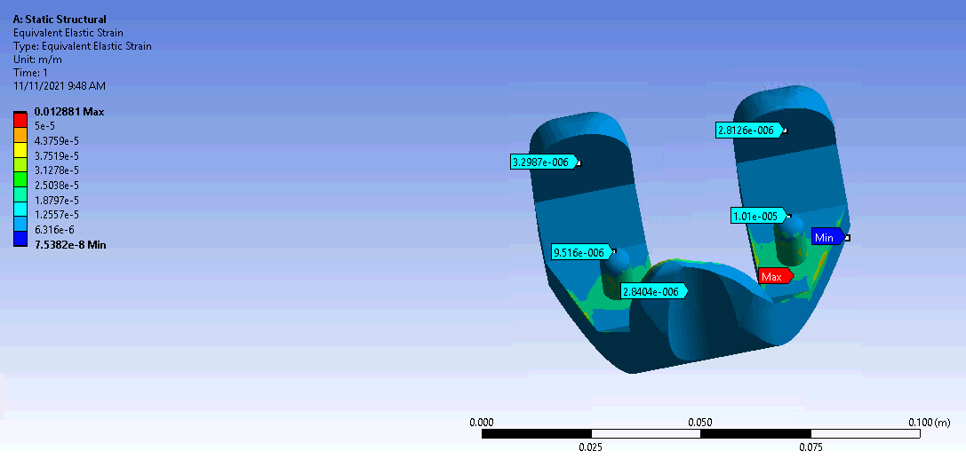
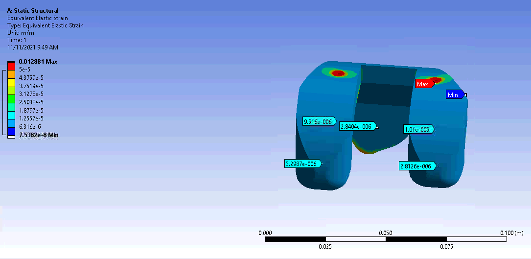
Looks like the two shafts of the knee implant are taking the brunt of the stress/strain and there’s some even spread. Not sure about the numbers but I reckon it looks alright :)